...

|
|---|
| Table of Contents |
|---|
Introduction
The module variant basic smart is a compact version for use in vehicles and machinery and wherever an access authorization is required.
...
Scheme
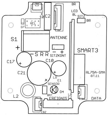
Motherboard basic smart
...
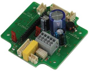
Motherboard assemby
...
Circuit diagram basic smart 3
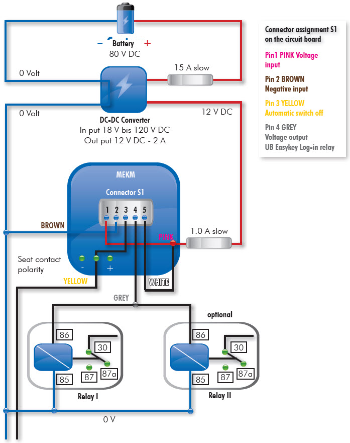
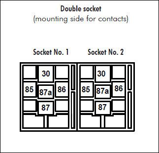
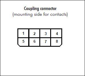
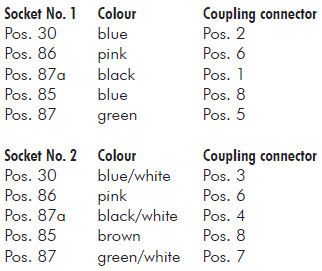
Terminal diagram for female connectors
Relay socket Version 1
E006-014
...
Installation instructions
...
Define installation point (if necessary make a bracket).
Note: The antenna cable is only about 1 meter long.
Install the module and secure it with at least 2 screws.
Before connecting to the mains the maximum
switching current must be measured.
Note: Relay contacts may only be loaded with a maximum of 60 Watt.
If the power is greater than 60 watts, an additional power relay must be used.
Relay contacts to be connected in series with the load.
For the power supply of the module insure that an 1 A slow fuse is fitted with the plus connection
(see diagram, page 4).
If a seat switch (SEAT) is used, the seat-contact bridge on the mother board must be wired up
(depending on the polarity).
If no seat switch (Seat) is used, the yellow cable must be wired to Negative (-).
The seat-contact bridge (Seatkont ) is also to be wired to Negative (-).
If Presence Detections is used, wire the seat-contact bridge (Seatkont) to Negativ (-).
- Install Antenna (Antenne) at the desired location.
Install Programming connector (DATA) easily accessible.
...
When using the Event Tool the user is alerted about an incident (damage) by a flashing blue LED.
Technical Data
| Measurements | 102 x 82 x 62 mm |
| Weight without connection cable | 310 g |
| Housing | Light grey, protection class IP54 |
| Mounting | with 4 screws possible |
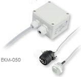
| Measurements of antenna | round 25 x 30 mm |
| Measurements of programming socket | round 28 x 40 mm |
| Temperature range | -10 bis +65° C |
| Relay | (potential-free), |
| Lenght connection cable | Approx. 3 m |
| On and off switch | Via user transponder, |
| Power supply | 10 – 30 V |
| Electricity consumption | < 100 mA |
| Transponder response range | Approx. 0 – 30 mm |
| Programming of user data | Via (RS 232) serial interface |
| Programming cable | Lenght approx. 1,5 m |
| Data retention | battery backed (approx. 5 years battery life) |
| Certificates | BZT |
Trouble shooting

Measure power supply
Unscrew module and remove cover.
At power supply connection (plug) measure voltage output on brown and pink wire.
A minimum output of 12 V must be measured.
...
Check relay contact
At power supply connection (plug) measure voltage output on grey and white wire.
After turning the transponder on the potential is transferred
Domnick+Müller GmbH+Co. KG Max-Planck-Straße 11 D-61381 Friedrichsdorf | BESTELLUNG SUPPORT HOMEPAGE |
|---|