EKM-300 technical description crash+remote
|
|
|---|
Introduction
The module crash+ has been adapted to current changes in the Machinery Directive.
From version crash + V / 2, the module has two relays, a „log- in relay“ and a „crash relay“.
The log in relay is switched on and off via transponder and replaces the mechanical ignition lock.
The crash relay is activated only in case of a crash and can perform the vehicle-specific shut down.
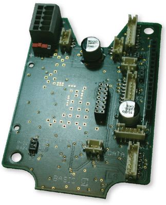
Motherboard crash+remote
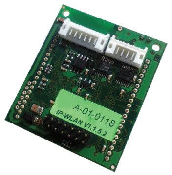
Interface circuit board WiFi
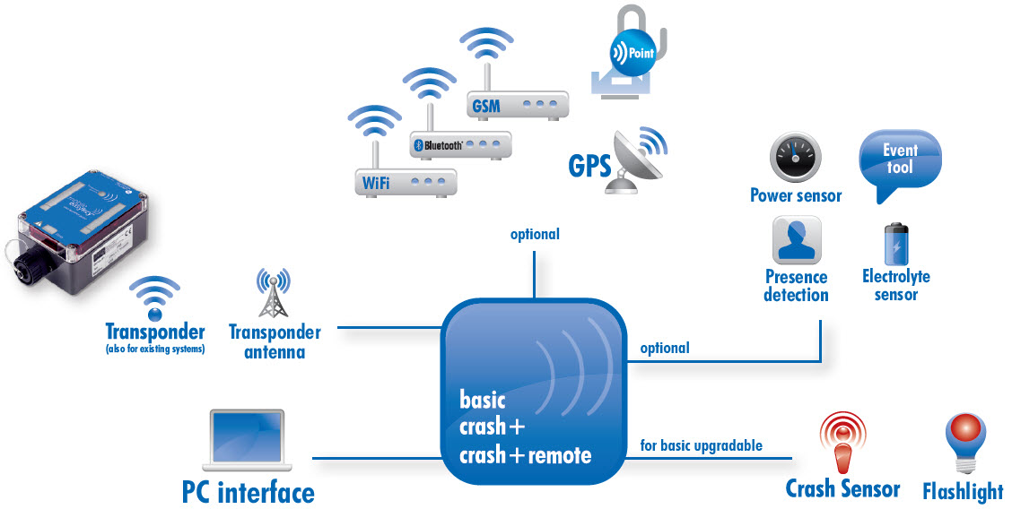
Scheme
Circuit diagram crash+remote
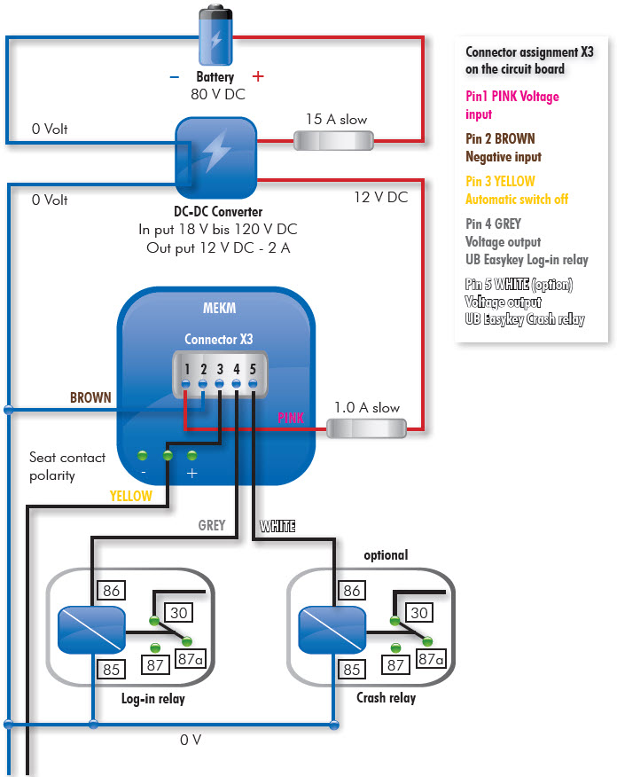
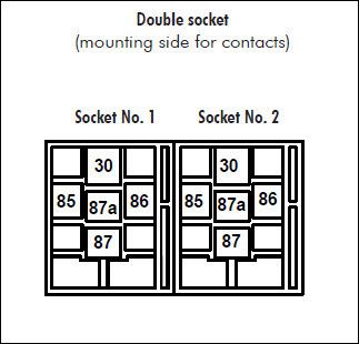
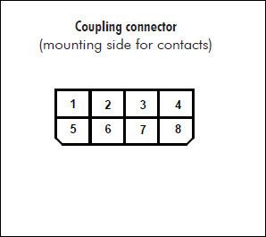
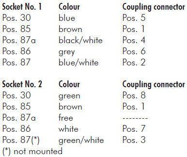
Connector assignment
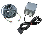
Double socket relay with connection cable
Relay socket version 2
E006-120
Modifications
- The circuit board has no more potential-free relay.
- There are now two relays (Log-in /crash relay) which when activated, switch the input voltage to the Easykey.
That means in detail:
- The grey cable of the Easykey is the positive polarity of the coil of the external electronic load relay.
With this external relay the ignition switch can be replaced. - The white cable of the Easykey is the positive polarity of the coil of the external crash load relay.
With this external relay, in the event of a crash, any function can be switched. - The output load is max. 200mA each (for the log-in and crash relay on the circuit board).
- With an input larger than 30 Volt DC a voltage transformer (Article number E006-010) must be installed.
- Note: The relays (log-in and crash relay on the circuit board) switch the input voltage “UB Easykey”
(e.g. 12 V or 24 V), therefore the external load relays must run the appropriate voltage.
Important:
If the presence detection is used together with radio data transmission, there must be a distance of at least 70 cm between the radio module and the presence detection in order to rule out interference
Circuit board WiFi
The circuit board between the WiFi module Matchport
b/g or b/g Pro and the motherboard was replaced by a new interface board.
The remote sensor is connected to the underside of the interface board (connector).
The connection of the programming socket (from the motherboard)
is also inserted on the underside of the interface board.
The interface board is only available as an active version.
During configuration with the service software “IP-WiFi” must be ticked.
Remote sensor
Learning while driving
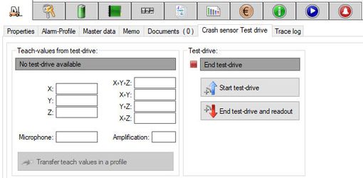
With a simple click, the „Start test-drive“ starts and after a short time, the first values are transferred directly into an existing or new profile.
Information can also be collected over a longer period of time – without any „crash-tripping“.
Evaluation and analysis
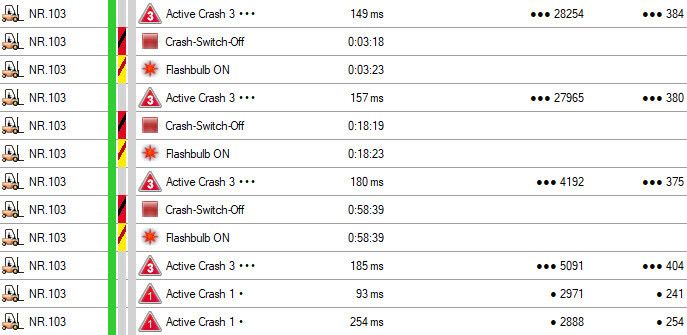
The logbook shows the level and strength of a crash.
Individual setting possibilities allow a variety of measures - from registering the crash in the logbook,
to being alerted by a flashing light up to the shutdown of the vehicle anything is possible.
The levels and values can then be conveniently compared and evaluated in Excel.
Installation is fast and easy
The acceleration sensor and the seismic microphone are quickly mounted and operational with plug connections.
The initial configuration is done via the Easykey manager and makes the vehicle immediately available.
Changes to the settings can then be made conveniently from your PC.
Technical data
| Measurements | 120 x 80 x 55 mm |
| Weight without connection cable | 620 g |
| Housing | Protection class IP54 |
| Housing | with 4 screws possible |
| Measurements of programming socket | round 28 x 40 mm |
| Temperature range | -10 bis +65° C |
| Relays | (potential-free), |
| Lenght of connection cable | Approx. 3 m |
| On and off switch | Via user transponder, |
| Power supply | 10 – 30 V |
| Electricity consumption | < 100 mA |
| Transponder response range | Approx. 0 – 30 mm |
| Programming of user data | Via (RS 232) serial interface |
| Programming cable | Length approx. 1,5 m |
| Data retention | battery backed (approx. 5 years battery life) |
| Certificates | BZT |
| Measurements of sensor | 80 x 75 x 55 mm |
| Length of connector cable | 4 m |
| Housing of sensor | Protection class IP 65 |
| Length of microphone cable | Standard 2 m (max. 4 m) |
Domnick+Müller GmbH+Co. KG Max-Planck-Straße 11 D-61381 Friedrichsdorf | BESTELLUNG SUPPORT HOMEPAGE |
|
|---|
Mobile Easykey GmbH
Max-Planck-Straße 11
D-61381 Friedrichsdorf
BESTELLUNG
bestellung@mobileeasykey.de
SUPPORT
khd@mobileeasykey.de
www.mobileeasykey.de