|
|---|
| Table of Contents |
|---|
...
- Define installation point
(if necessary make a bracket). - Install the module and secure it with
at least 2 screws . - Before connecting to the mains the maximum
switching current must be measured.
Note: Relay contacts may only be loaded with
a maximum of 60 Watt. - If the power is greater than 60 watts, an additional
power relay must be used. - Relay contacts to be connected in series
with the load. - For the power supply of the module insure that
an 1 A slow fuse is fitted with the plus connection
see diagram, page 3). - If a seat switch (SEAT) is used, the seat-contact
bridge on the mother board must be wired up
(depending on the polarity). - If no seat switch (Seat) is used, the yellow cable
must be wired to Negative (-). The seat-contact
bridge (Seatkont) is also to be wired to Negative (-). - If Presence Detections is used, wire the seat-contact
bridge (Seatkont) to Negativ (-)
Important:
If the presence detection is used together with radio data transmission, there must be a distance of at least 70 cm between the radio module and the presence detection in order to rule out interference
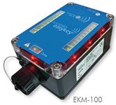
Technical data
| Measurements | 120 x 80 x 55 mm |
| Weight without connection cable | 490 g |
| Housing | Protection class |
| Mounting | with 4 screws possible |
| Measurements of programming socket | round 28 x 40 mm |
| Temperature range | -10 to +65° C |
| Relay | (potential-free), |
| Lenght connection cable | Approx. 3 m |
| On and off switch | Via user transponder, |
| Power supply | 10 – 30 V |
| Electricity consumption | < 100 mA |
| Transponder response range | Approx. 0 – 30 mm |
| Programming of user data | Via (RS 232) serial interface |
| Programming cable | Length approx. 1,5 m |
| Data retention | battery backed (approx. 5 years battery life) |
| Certificates | BZT, CE |
...